
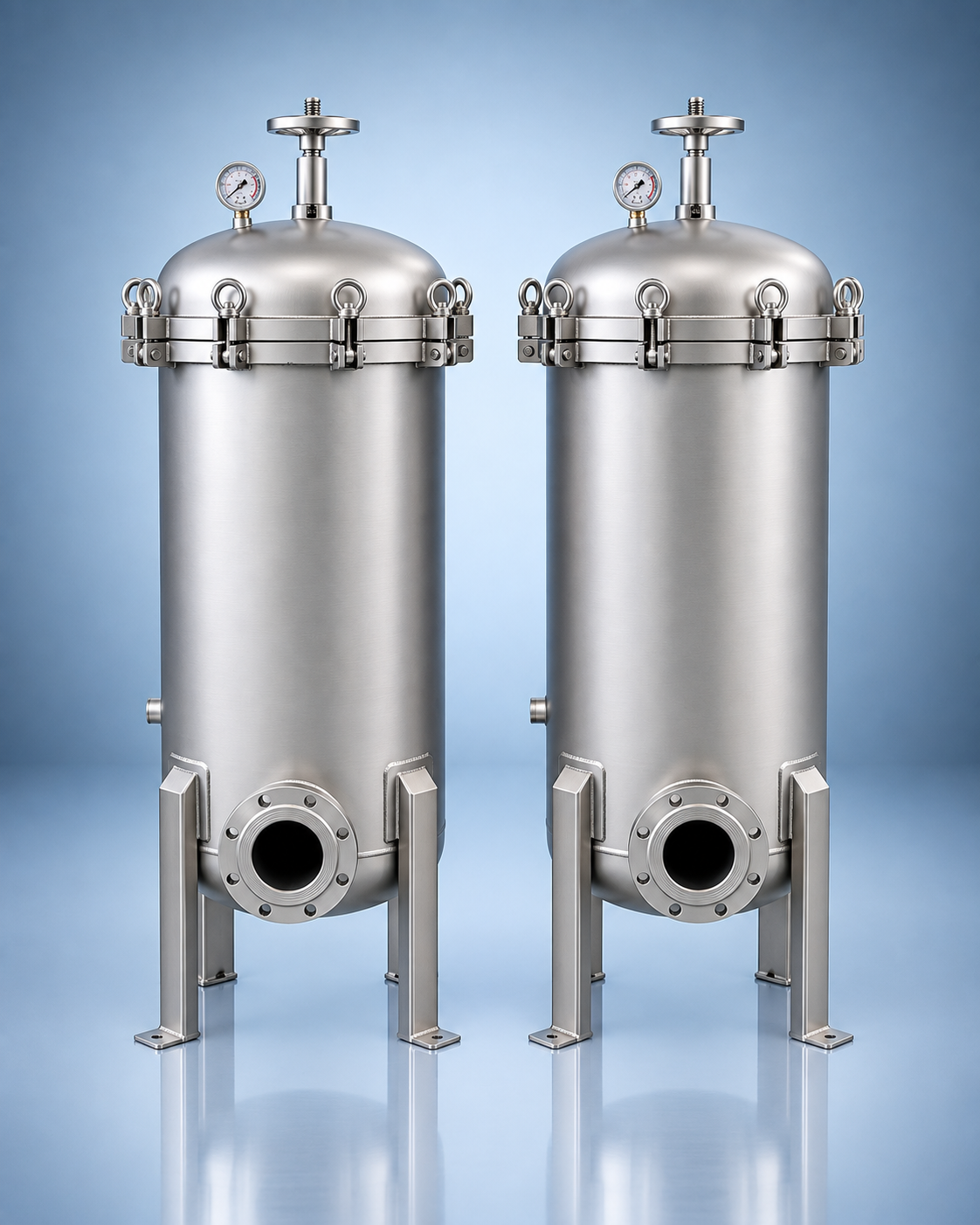
Vent and drain connections on a high flow filter housing are process and service interfaces, not decorative accessories. They affect filling, air removal, depressurization, product recovery, maintenance and personnel exposure. A quotation should therefore define what each connection must do, where the discharged fluid goes and how the housing is isolated before opening.
The featured image is a representative high flow cartridge housing. It does not prove a particular vent, drain, pressure code, port size or internal arrangement.
Define the operating sequence first
Provide a simple written sequence for start-up, normal operation, shutdown and cartridge change. Identify which valves are open or closed, where displaced gas is routed and how the operator verifies atmospheric pressure before opening the closure. An approved P&ID and operating procedure remain the controlling documents.
Parker vessel manuals give manufacturer-specific examples: during filling, a manual air eliminator may be left open until liquid appears, and during cartridge change the pump and inlet/outlet valves are shut before drains and the air eliminator are opened. These examples show why venting and draining belong in the operating sequence; they are not universal instructions for an unrelated housing.
Vent RFQ fields
| Field | Buyer input | Design question |
|---|---|---|
| Function | Initial air release, routine bleed, depressurization, gas collection or CIP/SIP duty | Manual, automatic or connected to a closed system? |
| Location | Required high point and housing orientation | Can trapped gas remain above the cartridge plate or closure? |
| Connection | Size, thread/flange/clamp standard, rating and material | Does it match the plant valve and tubing standard? |
| Discharge | Atmosphere, safe container, recovery header or treatment system | Could the released gas or liquid be hazardous, hot or valuable? |
| Instrumentation | Pressure gauge/transmitter, bleed valve, sight indication or interlock requirement | How will zero pressure and full filling be confirmed? |
For connection standards, refer to the NPT, BSP and flange RFQ guide. Do not specify “standard vent” without identifying the applicable piping standard and duty.
Drain RFQ fields
A low-point drain should address the actual vessel geometry, nozzle orientation and internals. State whether the goal is product recovery, complete maintenance drainage, flushing, sampling or routine water removal. Include allowable retained volume when complete drainage is important, plus the required slope, valve type and discharge routing.
- Fluid name, solids, temperature, viscosity, corrosivity and exposure controls.
- Drain connection size/standard, material, valve and removable spool or hose interface.
- Quantity and location of drains when chambers, sumps or horizontal geometry create separate low points.
- Destination, backpressure, containment, neutralization and waste classification.
- Flushing or cleaning connection, cleaning fluid and required recovery procedure.
- Freeze protection, insulation or heat tracing where the process specification requires it.
A drain port by itself does not guarantee complete drainability. The approved fabrication drawing should show the vessel slope, lowest internal point, support legs, floor clearance and access to the valve.
Isolation, depressurization and service safety
Before the housing is opened, the operating company must apply its own isolation and lockout/tagout procedure. The RFQ should state whether double isolation, bleed, bypass, block-and-bleed or a closed discharge system is required. It should also identify stored-energy risks, hazardous vapors and the method for proving zero pressure. Never rely only on a pressure gauge reading or assume that opening a vent is safe for every process fluid.
Include the maximum operating and design conditions in the filter housing pressure data sheet. Maintenance space, cover movement and lifting are covered in the maintenance-clearance guide.
Coordinate the ports with the cartridge and housing arrangement
A High Flow Filter Housing may be vertical or horizontal and can use different internal supports and cartridge families. The vent must not interfere with closure handling, and the drain must remain accessible after insulation, platforms and piping are installed. Provide the high flow cartridge family, quantity, length and flow direction because the internal arrangement affects filling and service.
Quotation package
- P&ID, equipment data sheet and general arrangement drawing.
- Fluid, solids, gas/vapor hazard, temperature, viscosity and cleaning media.
- Normal/design pressure and temperature, vacuum case and applicable code.
- Start-up, shutdown, drain and cartridge-change sequence.
- Vent/drain function, location, connection, valve, instrumentation and discharge destination.
- Housing orientation, cartridge family/quantity, piping loads and service clearance.
- Material, corrosion allowance, surface finish, NDE, testing and document requirements.
Source notes
- Parker filter vessel installation and operation manual: manufacturer-specific filling, venting, draining and cartridge-change sequence.
- Parker PECO Model 110H instructions: manufacturer example covering venting during filling and drain/vent use during depressurization.
Send your specification for review
Send the P&ID, fluid and hazard data, housing orientation, cartridge family, operating sequence, vent/drain duties, port standards, discharge routing and documentation requirements for review.
Frequently asked questions
Does every high flow filter housing need both a vent and a drain?
The required connections depend on orientation, fluid, filling method, maintenance sequence and code. The design should provide a safe way to remove trapped gas, depressurize and drain the actual vessel geometry.
Can the vent discharge directly to atmosphere?
Only when the process hazard assessment and site procedure allow it. Hot, toxic, flammable, odorous or valuable fluids may require a closed collection or recovery route.
What drawing is needed to quote vent and drain connections?
Provide a P&ID and general arrangement showing orientation, elevations, nozzles, closure, supports, platforms, discharge destinations and required service clearances.

 WhatsApp