
A stainless steel mesh part can meet the aperture requirement and still fail assembly because the edge, burr condition, flatness or joining method was not defined. OEM buyers should therefore specify the finished component, not only the roll-mesh grade.
This guide explains stainless steel filter mesh edge finishing and cutting choices for discs, strips, cylinders and framed parts. The suitable method depends on the alloy, wire diameter, weave, number of layers, geometry, volume and assembly process.
Start With the Finished-Part Drawing
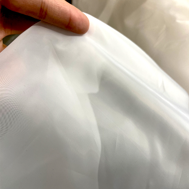


The drawing should identify the outer dimensions, holes, cut-outs, orientation, datum, tolerances and edge condition. For a roll or simple cut piece, start with INCE stainless steel filter mesh. For shaped components, review filter mesh discs and custom mesh fabrication.
| Method | Typical procurement reason | Points to define |
|---|---|---|
| Shearing or blade cutting | Straight strips and economical cut-to-size pieces | Direction, squareness, edge distortion, loose wires and allowance for later framing |
| Stamping or punching | Repeatable discs or shapes at production volume | Tooling, burr direction, distortion, nesting, first-article approval and tool ownership |
| Laser cutting | Complex profiles and accurate cut paths | Heat-affected edge acceptance, discoloration, dross, layer movement and cleaning |
| Waterjet or other non-contact cutting | Shapes where heat input is undesirable | Kerf, edge condition, abrasive contamination, drying and final cleaning |
| Welding or edging | Joining layers, forming cylinders or adding a rigid border | Weld type, overlap, seam position, frame material, distortion and inspection |
Edge Condition Changes the Assembly Result
A buyer may request “no sharp edges,” but that phrase is difficult to inspect without an agreed reference. Define whether the part may have loose wire ends, whether the perimeter will be captured by a frame, whether the mesh must be safe for manual handling, and whether the edge must be sealed or welded.
For fine or multilayer mesh, also state whether layers may shift during cutting. When a support layer is used, identify the stacking order and which surface faces the process. A drawing note such as “trim flush after welding” is more useful than a general request for good workmanship.
Welding and Framing Questions
- Is the mesh a single layer, a spot-welded stack or a bonded/sintered laminate?
- Should a cylinder use an overlap seam or a butt seam?
- Is the edge captured in stainless strip, wire, perforated plate or a machined ring?
- Which alloy is required for the mesh, frame and filler material?
- Are weld discoloration removal, pickling or passivation required?
- What flatness, concentricity or leak path must be checked after joining?
Official Fabrication Examples
Haver & Boecker describes wire-mesh fabrication with rotary and stationary cutting, splitting, waterjet, plasma and laser processes, plus welding and moulding. Its metal-filter pages also show discs, cut pieces, deep-drawn parts, cylinders and cartridges. These examples confirm the range of manufacturing routes, but they do not establish a universal tolerance or edge quality for every mesh.
Inspection Plan for OEM Mesh Parts
- Verify alloy, weave, aperture or mesh count and wire diameter against the agreed specification.
- Measure the finished outline from defined drawing datums.
- Inspect edge burrs, loose wires, delamination and distortion using agreed acceptance samples.
- Check weld position, overlap, continuity and heat distortion where joining is used.
- Approve a first article or golden sample before releasing a production lot.
- Define packaging that prevents bending, abrasion and mixing of similar parts.
Source Notes
Manufacturing references: Haver & Boecker metal filters and fabricated parts, Haver & Boecker production depth and Haver value-added processes.
Frequently Asked Questions
Which cutting method is best for stainless steel filter mesh?
There is no universal best method. Geometry, wire size, weave, layer count, tolerance, edge requirement, volume and downstream joining determine the choice.
Does laser cutting guarantee a burr-free edge?
No universal guarantee should be assumed. Define the acceptable heat effect, dross, loose wires, discoloration and cleaning requirement on the drawing.
What should an OEM mesh RFQ include?
Include the drawing, alloy, weave, aperture or mesh count, wire diameter, layers, edge condition, joining method, tolerances, inspection and packaging.
Send an OEM Mesh Drawing
Submit your drawing, expected annual quantity, material and inspection notes through Get OEM Pricing. INCE can review manufacturability and identify which tolerances or edge requirements need clarification before quotation.
 WhatsApp